Found lighting the bulbs challenging? And, thinking how do you wire a photocell? Maybe, you are ignorant about the wiring of lighting contactors, aren’t you?
Then, this article is solely for you! We have prepared an informational diagram with a briefing on this topic.
So, what happens in the lighting contactor wiring diagram with photocell?
Well, the diagram deals with a circuit breaker, power contactor, and photocell sensor. A neutral wire, live wire along with load wire get every component connected together. And the power moves from the circuit breaker directing forward to the power contactor. Then, bulbs get activated.
But these are not everything. Read this article till the end to find in-depth research on this. So, let’s get going!
Lighting Contactor Wiring Diagram With Photocell: Explained!
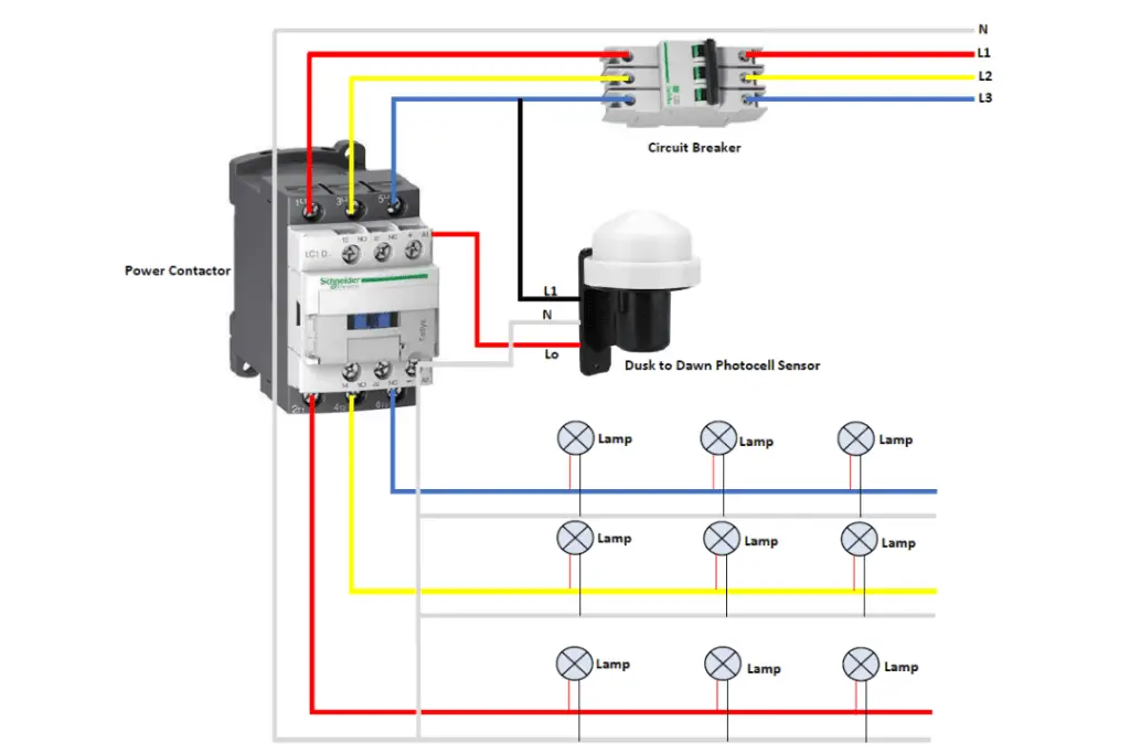
For your better understanding, here we have attached the whole diagram. It starts from the power contactor and ends up connecting the photocell. You will also know how to wire a photocell to a led light.
Meanwhile, the key components inside this are:
- Circuit breaker
- Power contactor
- Photocell Sensor
- Lamps
Now you know all the parts that put major effects on this whole process. But how is a photocell switch connected here to a 3-phase contactor?
Well, seeing three wires coming from the “dust to dawn” photocell sensor? Basically, L1 represents the live wire.
In the meantime, N comes into the picture for the neutral wire. Along with that, load wire is identified here with Lo.
This particular wire can empower the contactor coil. Relevantly, it has got the ratings for phase voltage.
These can be L1-N or L2-N or even L3 -N. In the meantime, 120, 208, or even 240 volts are the most common phase voltage levels.
As shown in the diagram above, power moves to the circuit breaker. This breaker can manipulate overloading. Your motor will get short-circuit protection too from this.
But how do you wire a photocell to an outside light? Basically, power then moves toward the contactor from the circuit breaker. Here, it could be in 25 Amp breaker wire sizing.
Meanwhile, the photocell sensor has a unique trait. It remains off during daylight.
As a result, the lamps will be shut down too. That’s how to wire a photocell to multiple lights, not just the outside lights.
However, the sensor will get activated at night by providing light to the lighting loads. Now, you know how to wire a photocell to an outside light, don’t you?
How to Wire a Lighting Contactor With a Photocell? [Step by Step]
No more thinking about how do I wire a photocell! Here’s a quick step-by-step briefing of the process!
Step 1: Switch Off the Electricity
Initially, shut every electrical power down to the light fixture. It should be done where you will be installing the photocell.
Step 2: Extraction
Take a screwdriver and extract the light out of the electrical box. Before extracting, check if the G clip electrical box repair is required or not!
Step 3: Wiring Nuts Removal
Now, focus on the wires to the power supply along with the light fixture. There are two wire nuts available joining which need to be pulled out.
And, install the fixture on a flat surface so that the installation process goes smoother.
Step 4: Hole for Photocell
It’s time to remove the connecting holes located in front of the outdoor light fixture. Simply tip in the hole with a screwdriver to extract this metal knockout body.
And, put the metal end of the photocell into that hole.
Step 5: Tightening Switch
Now, tighten up the switch and nut by utilizing wire pliers.
Step 6: Three Wiring
You should join all three particular wires to the photocell switch. The white one is neutral, black wire works as the main power source.
And, the red represents the photocell switch wire. Once you complete joining, you know the answer to how to wire outdoor light with photocell!
Step 7: Connection to Box
Lastly, connect the electrical box to the fixture. Now, replacing the light bulb of the lighting fixture is completed.
So, that’s how you can wire the lighting connector.
Frequently Asked Questions (FAQs):
What Do A1 And A2 Represent On A Contactor?
A1 and A2 on a contactor indicate the electromagnetic coil assembly’s both ends. You will mostly find contactor manufacturers utilizing A1 and A2. These are meant to represent the two terminals. While one terminal comes with electrical power, the other one consists of the contactor’s magnetic coil.
Can One Photocell Command Multiple Circuits?
Absolutely, yes! One photocell is capable of controlling multiple circuits as long as they’re at the same line. It controls how to wire a photocell switch manually and does turn off/on these circuits. Photocells can fulfill the need without someone going outside to activate outdoor lights manually.
How Does A Contactor Operate For Lights?
Contactors work like relay switches. Maintaining the electric discharge through a circuit pushing the lighting in a particular zone. These can exist remotely while controlling circuits carrying higher voltages. However, this circumstance might put danger to the operation while controlling directly.
What Is The Red Wire For On A Photocell?
The load line wires come as red in most photocells. Neutral wires might come in a white variant and the supply line wires are black. Light dropping on the photocell during sunlight forces the street lights to shut off. And, these get turned on at night. And, energy gets saved during the daylight.
How Can I Test A Photocell?
Connecting a multimeter in a resistance-measurement manner to the two leads comes first to test. You need to check how the resistance transforms while shading the sensor via hand. It can be measured by turning off lights too. Knowing also how to wire a photocell to an outlet is vital here.
What Do L And T Mean On A Contactor?
The “L” stands for “line” which basically indicates the incoming supply line. For the loading side, you already get to see another meaning for “L”. So, there exists “T” meaning “terminus”. This means the exit point. L and T can be 1, 2, 3, and so on. T is the last point connecting in the circuit.
Final Words
Now you know how the lighting contactor wiring diagram with photocell. We hope that we could reduce your confusion regarding this mechanism. And most importantly, you have found the required answers.
Get anything in your mind? Don’t forget to let us know!
That’s all for today! Best of luck!
Hey, I’m Steven Jones, the founder, and writer of this site. I have worked in Electrical for the past 5 years. I also know how to save energy and how to troubleshoot our electrical devices. I hope you enjoy my blog.